Automatic Water Supply Routing — Cold Water and Hot Water
What it does
In this scenario, Automatic Routing creates both water supply networks and inserts the transitions required between the selected materials. The example uses a bathroom with a shower and a bidet spray served by hot water.
Scenario used in this tutorial
The room must contain at least one fixture requiring hot water, such as a shower, lavatory, bathtub or bidet spray, in addition to the fixtures served by cold water.
Before you start
- Room definition procedure completed.
- Routing families mapped and loaded.
- Cold water and hot water pipe types available.
- Valves, mixer tap or single-lever tap mapped.
- Room and fixtures positioned in the model or link.
- Plan view of the correct level open.
- License with Plumbing · Automatic Routing active.
How to run it
- Open Automatic Routing. In the Fluxor ribbon, Plumbing panel, click Automatic Routing. The wizard window stays open while you interact with the plan.
- Select the room. In the Room card, select the bathroom you want. Fluxor highlights the outline in green; use the view button to frame it in the view.
If the room does not appear, stop here and follow the article How to define rooms.
- Choose Cold Water and Hot Water. In the Systems card, tick Route water supply network and select Cold Water + Hot Water. Leave the drainage network unticked to run only the scenario in this article.
Choose the routing mode:
- Through the wall — for points concentrated on one wet wall.
- Through the floor — to distribute the trunk below the floor.
- Mixed (Wall + Floor) — for rooms with more than one wet wall.
ℹ️ Note: in Through the floor mode, you can enable the Resolve interferences automatically option. When ticked, Fluxor creates detours in the pipework to avoid the beams identified along the path — from the Revit model itself or from IFC links. After routing, review the detours that were created.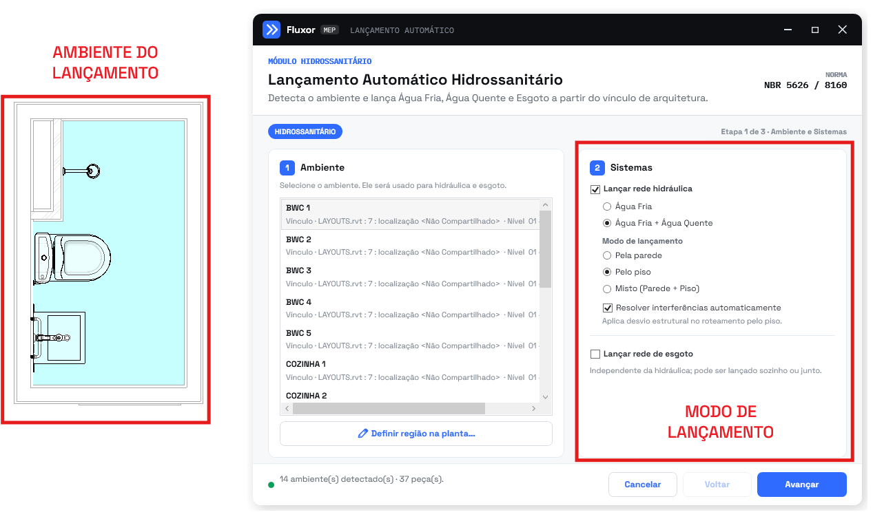
- Configure the materials of both networks. Select:
- Pipe type — Cold Water, usually solvent-weld PVC;
- Pipe type — Hot Water, in CPVC or PPR;
- diameter of the branch or riser of each network;
- depth of CW and HW, when the mode is Through the floor.
Fluxor suggests the diameter according to the material, but the selection can be changed to match the project standard.
- Set risers, valves and the shower control. Choose between creating the risers automatically or picking existing risers manually. Then check:
- gate valve for the cold water riser;
- gate valve for the hot water riser;
- shower control: Single-lever or Mixer tap;
- bidet spray control, where applicable.
Water supply network configuration and fixture selection. At this step, configure the cold water and hot water networks separately. Select the pipe type, the diameter of the branch or riser and the depth of each network. In the example, the cold water pipework sits 10 cm below the finished floor and the hot water pipework 15 cm, keeping the networks at different levels.
You can also define the risers manually or keep the automatic placement, as well as insert and select the gate valve.
In the Fixtures in the room list:
- In the model (automatic): fixtures that already exist in the project are used directly, without duplication.
- From the link (selectable): choose which architectural fixtures should be imported and considered in the routing.
- Use: copies the original fixture from the link.
- Replace: swaps the fixture for a compatible family from the template.
The HW badge marks a fixture with a hot water supply, whose original family is preserved to keep the connectors correct. The preview at the bottom shows the source fixture and the chosen target. After checking the settings and the selected fixtures, click Next.
ℹ️ Note: before moving on, resolve every item in the Families missing for this routing panel using Load, Load all or Find.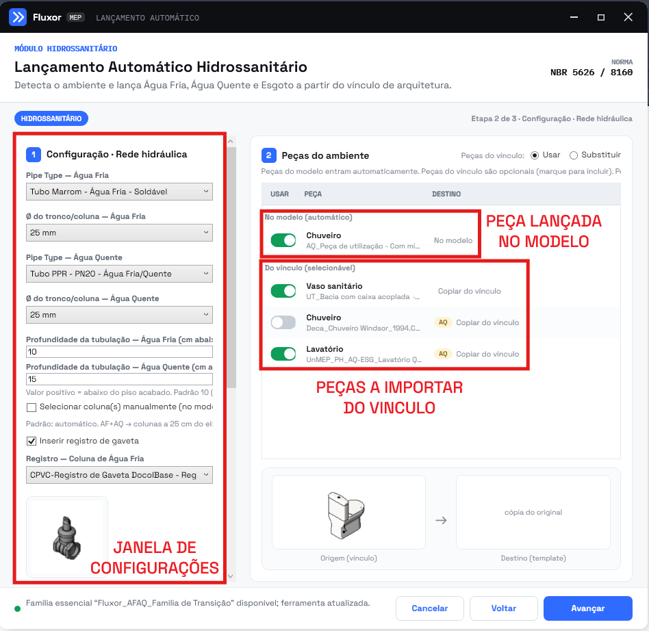
- Review and run. In the summary, check the room, mode, materials, diameters, risers, valves, shower control and fixtures. Click Run and pick the final points requested on the plan.
- Confirming the wet walls. At this step, the plugin automatically identifies the wet walls, that is, the stretches of the room perimeter where the plumbing fixtures are located.
In the preview:
- Blue: wet walls detected automatically.
- Red: the remaining segments of the room perimeter. Red does not indicate an error.
In the image, the plugin recognized mainly the left side wall, where the plumbing fixtures are positioned. Check that the stretches highlighted in blue correctly match the locations of the fixtures.
Click Yes to accept the detection. The blue walls will be used as the reference for routing and for the cold and hot water pipe connections.
Click No if a wet wall is wrong or was not identified. Then select the corresponding lines manually and press Enter to confirm.
In the example, the automatic detection did not include the small horizontal stretch shown in the image. That is why it was necessary to click No, select that stretch of wall manually and press Enter to add it to the wet walls.
The colored lines are only temporary guides and are removed automatically after confirmation.
💡 Tip: during manual selection, click the colored perimeter lines, not the model walls directly. Zoom in if you need to select a stretch more precisely.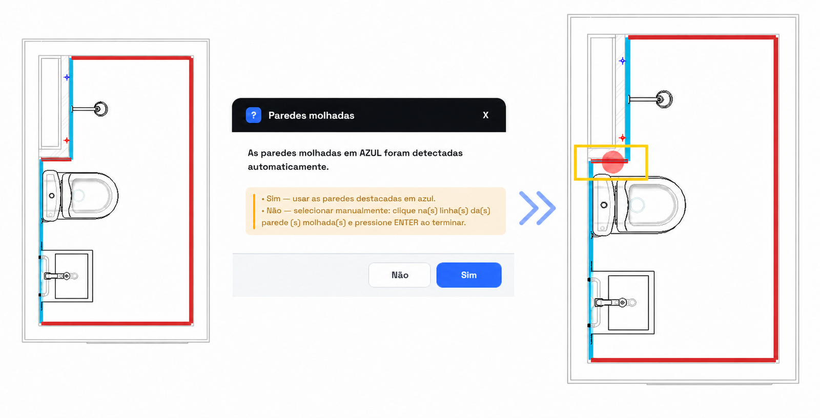
- Checking the routing result. Once processing finishes, the plugin shows a summary of the room detection and of the preparation of the fixtures used in the routing.
On the plan, the created network is displayed in the system colors:
- Blue: cold water pipework.
- Red: hot water pipework.
The window shows the following data:
- Rooms detected: number of rooms processed. In this example, one room was used.
- Fixtures detected: total fixtures found while scanning the model and the links.
- Imported: fixtures copied from the link into the current model.
- Already in the host: fixtures that already existed in the current model and were reused.
- Skipped: fixtures that did not take part in the routing or did not meet the defined criteria.
- Errors: fixtures that failed during import or preparation.
In this example, 37 fixtures were detected during the scan. Of the fixtures selected for the room, three were imported from the link, none already existed in the current model and there were no skipped fixtures or errors.
Click Close to end the command and inspect the modeled network.
The Step 1 complete message mainly presents the result of the detection and import of the fixtures. The values shown do not represent the number of pipes, fittings or accessories created.
⚠️ Warning: if the Errors field shows a value greater than zero, check the fixtures in the model and consult the log file generated by the plugin.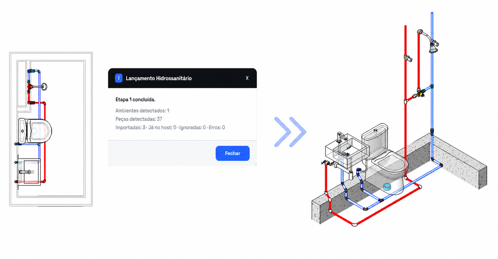
Common errors
| Symptom | Likely cause | Solution |
|---|---|---|
| Hot water is not created | The Cold Water + Hot Water option was not selected | Go back to the Systems card and tick the option |
| The shower control does not appear | Fixture without hot water demand or role not mapped | Check the fixture and the Mapping |
| Hot water fittings missing | The chosen material has no compatible families | Load the CPVC or PPR families |
| Risers swapped or out of position | Automatic placement unsuited to the room | Use manual riser selection |