Automatic Drainage Routing — Sanitary
What it does
Automatic Routing creates the sanitary network from the fixtures present in the room, including the toilet spine, branches, fittings and slope. In this article, the drainage network is run separately from the water supply networks.
Scenario used in this tutorial
The example uses a bathroom with a toilet, lavatory, shower, drain and floor drain box positioned inside a room recognized by Fluxor.
Before you start
- Room definition procedure completed.
- Routing families mapped and loaded.
- Drainage pipe type and fittings loaded.
- Sanitary fixtures with valid connectors.
- Room existing in the model or link.
- Plan view of the correct level open.
- License with Plumbing · Automatic Routing active.
How to run it
- Open Automatic Routing. In the Fluxor ribbon, Plumbing panel, click Automatic Routing. The wizard window stays open while you interact with the plan.
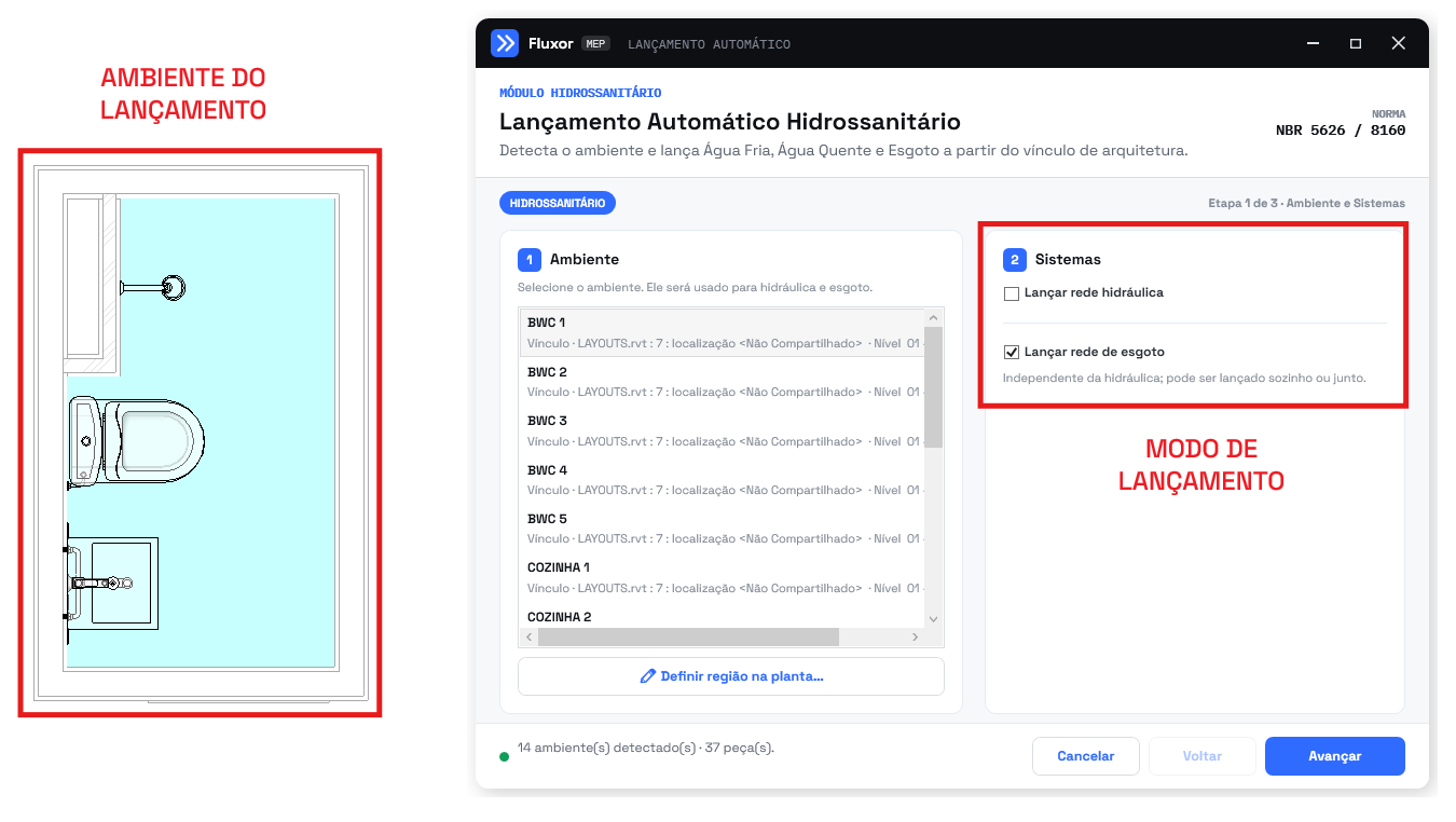
- Select the room. In the Room card, select the bathroom you want. Fluxor highlights the outline in green; use the view button to frame it in the view.
If the room does not appear, stop here and follow the article How to define rooms.
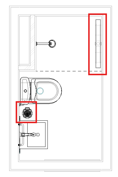
- Place the boxes and drains in the room. Before running the automatic routing, insert into the model the boxes and drains planned for the room, if any.
In this example, a trapped floor drain and a linear drain for the shower area were placed.
- Choose Drainage only. In the Systems card, leave Route water supply network unticked and tick Route drainage network. The wizard will then show only the sanitary routing settings covered in this article.
Drainage routing is independent of the water supply networks and can be run on its own or together with them.
- Configure the pipe type, the elevation and the fixtures. Select the Pipe Type — Drainage to be used, usually a PVC drainage pipe. Then enter the network elevation relative to the level.
Negative values place the pipework below the level. In the example, the value –30 cm means the main drainage network will be routed 30 cm below the reference level.
Where available, also configure the additional options:
- Include trap on the washing machine: shown when the room has a washing machine. When enabled, the plugin includes the assembly needed to connect the fixture to the drainage network.
- Coordinate the sink outlet: makes the plugin check the sink outlet area and adjust the layout when a beam interferes with the path. Instead of going straight through the structure, the tool tries to create a detour to route the pipework. Even with this option enabled, check the result in the 3D view.
- Realistic preview: when enabled, shows a preview with the pipe diameter and fittings represented closer to the final result. When disabled, the plugin uses simplified lines, which are lighter and faster to display.
Realistic preview only changes how the preview is displayed; the final routing still uses the pipe type and fittings defined by the tool.
In the version shown, Realistic preview is disabled by default. Enable it when you want a closer look at pipes and fittings before running. On larger or heavier models, keep it off for a faster preview.
In the Fixtures in the room list, tick the fixtures that will connect to the drainage network. Fixtures that already exist in the project are used directly. For elements from the link, choose between Use, to copy the original family, or Replace, to use a compatible family from the template.
Pay particular attention to the toilet, the lavatory, the drains and the floor drain box.
ℹ️ Note: if a fixture does not appear, confirm that it is inside the room, has connectors and is correctly classified in the Mapping.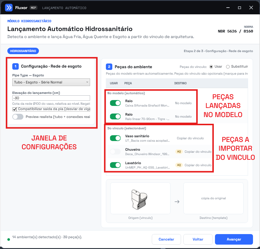
- Review and run. Check the room, the material, the elevation and the selected fixtures. Click Run to start the routing and follow the prompts shown on the plan.
- Set the target for the toilet's Ø100 pipe. At this step, tell the plugin where the main Ø100 drainage pipe coming from the toilet should be routed. The target can be a free point, a dedicated stack or a riser shared between different levels. Choose the option that best suits how the project's sanitary network is organized.
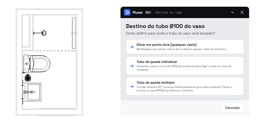
7.1 Click on a free point
Use this option when no stack has been modeled yet or when you want to set the network's arrival point manually.
After selecting the option, click on a free area of the plan. The point you pick is used as the reference for the Ø100 pipe's target.
This alternative suits early studies or situations where the riser will be modeled or connected later. After routing, check the position and complete the network's continuity if needed.
7.2 Individual stack
Select this option when a Ø100 pipe already exists dedicated to the room or to the sanitary group being routed.
After choosing the option, click the existing stack. The plugin routes the network to that element and makes the connection at the configured arrival elevation. Since an individual riser starts at that point and does not continue above it, the end is closed with an elbow.
Before confirming, check that the selected pipe has the correct diameter and position.
7.3 Shared stack
Use this option to connect the network to a through riser, which continues both to the level above and to the one below and can receive contributions from different rooms or floors.
Click the existing Ø100 riser. The plugin enters the network through a simple 45° junction, preserving the vertical continuity of the stack.
Before confirming the connection, move the cursor or press Tab to flip the junction direction. Choose the orientation that best fits the network path and check the result in a 3D view.
7.4 Choose and adjust the pipe route
Once the pipework target is set, the plugin shows a preview of the layout on the plan. The Drainage — Route panel reports the active option and lets you compare or adjust the path before the pipes are actually created.
The line shown at this step is only a preview. The elements are modeled after the route is confirmed.
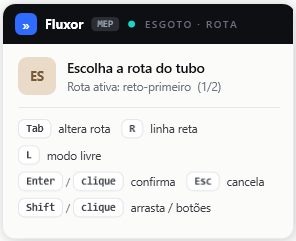
Use the following commands:
- Tab — change the route: cycles through the paths calculated automatically by the plugin. Depending on the target position, options such as straight first or diagonal first may be offered.
- R — straight line: forces a direct path between origin and target. Use this option when there is free space and no detours are needed.
- L — free mode: lets you draw the path manually, setting intermediate points. Click to add each point and press Enter to finish. Use Backspace to undo the last point and press L again to leave free mode. The plugin assists the drawing with 45° and 90° alignments.
- Enter or click — confirm: accepts the route shown and continues the routing. In free mode, clicking adds points; you finish with Enter or Ctrl + click.
- C — aim at the riser: shown when a riser is available in the room; directs the route to the riser instead of to the horizontal target under the cursor.
- Esc — cancel: interrupts the route selection without confirming the layout.
- Shift + click: hold Shift to temporarily freeze the modeling and enable interaction with the panel. In that state, you can drag the window or use the buttons it shows.
Before confirming, press Tab to compare the available routes and choose the path that best fits the space and the project's clashes. When the preview is right, press Enter or click in the view to continue.
7.5 The panel for the remaining fixtures: queue and targets
Once the toilet's Ø100 network is done, the plugin moves on to model the other selected fixtures — floor drain box, drains and lavatory — one at a time. The panel is still the same, but gains two new elements: the step title, which reports which fixture is being modeled, and the numbered queue of pending fixtures, with the current one highlighted. Just below the title, Active route indicates which of the calculated paths is drawn on the plan (for example, straight-first (1/2)).
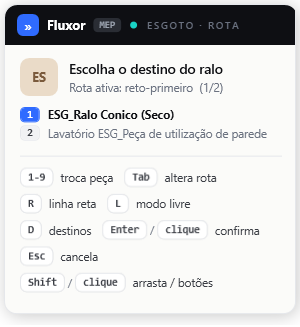
Besides the commands already described, this panel offers:
- 1-9 — switch fixture: leaves the current fixture without creating anything and jumps to the fixture with that number in the queue. The sequence continues from there and each fixture is modeled only once. Use it when you want to resolve first the fixture that defines the rest of the layout.
- D — targets: opens the list of possible targets for the fixture being modeled — floor drain box, drain or collector. Use it when the target you want is far from the cursor or when the connection has to enter through a junction on the 45° elbow.
While modeling these fixtures, bringing the cursor near a floor drain box makes the pipe end snap to it. While the target is snapped, the line shown is the real route to the box inlet and Tab switches between those routes; moving the cursor away releases the snap.
ℹ️ Note: the panel only shows the keys that are valid for the fixture being modeled. Fixtures that do not rotate, have no riser nearby or offer no target list do not show the corresponding shortcuts.7.6 Routing with a free-point target
The example shows routing with a free-point target, suitable when no stack exists yet or when the designer wants to set manually where the Ø100 network should arrive.
Select Click on a free point and pick the target on the plan.
Check the route the plugin proposes. Use Tab to switch the path, R for a straight line or L to draw a free route.
Confirm with Enter or a click. The plugin then continues with the connections for the remaining selected fixtures.
When it finishes, review the summary and click Close.
Check the result in 3D, looking at fittings, slopes and possible clashes.
ℹ️ Note: the free-point target defines where the network will end. The L shortcut lets you add intermediate points to the path.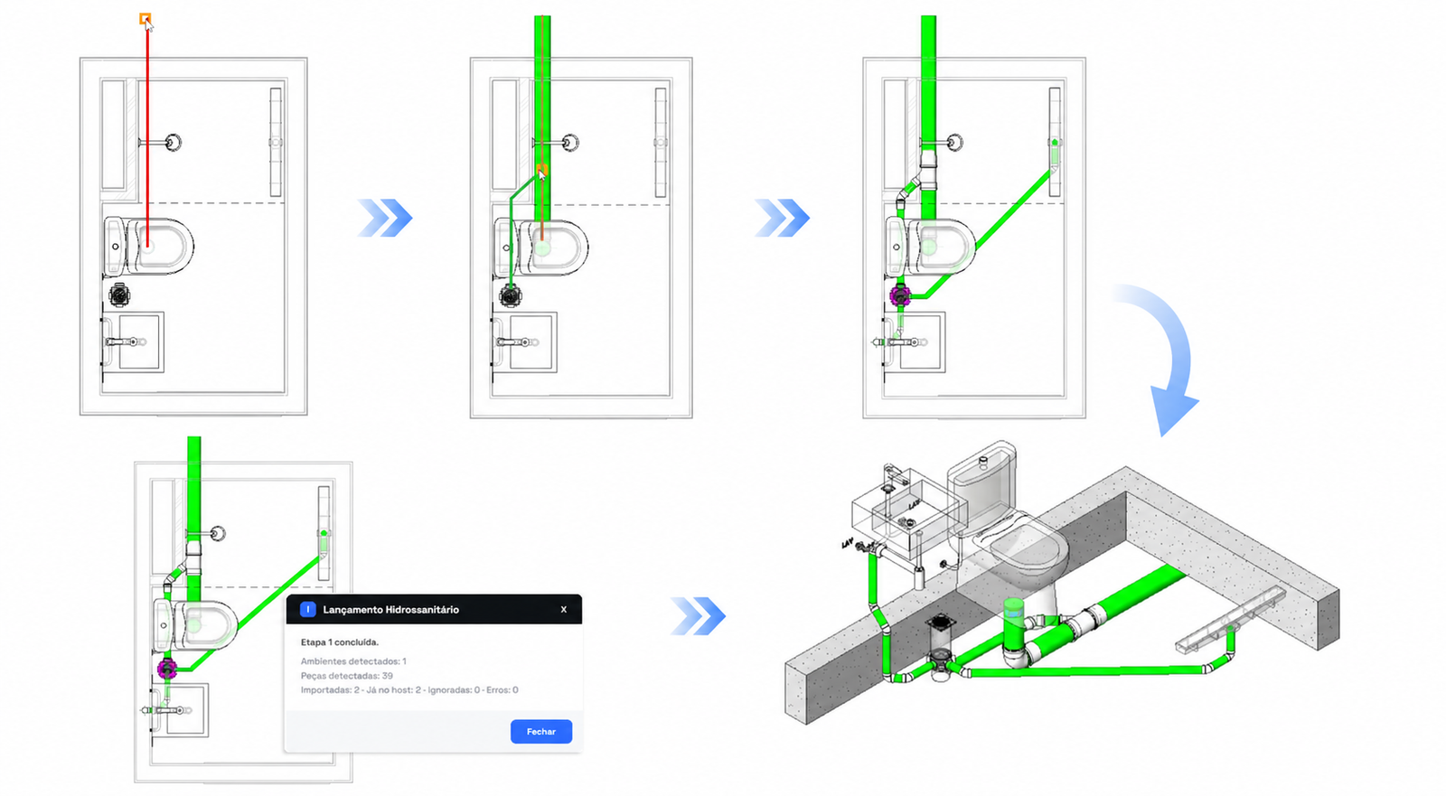
Common errors
| Symptom | Likely cause | Solution |
|---|---|---|
| The toilet does not connect to the network | Target or outlet direction not defined | Run it again and pick the target requested |
| A fixture does not show up in the table | Missing connector, wrong classification or fixture outside the room | Check the family in the Mapping |
| Drainage without adequate fall | Elevation incompatible with the path | Adjust the elevation or use Adjust Drainage ▸ Slope |
| The route clashes with a beam | Path without free space | Adjust the outlet or use the coordination option where available |
| Warning about connections that did not close at the end | One or more ends were left unconnected during routing | The pipes were created: check the ends named in the warning and adjust, or redo the run choosing another layout with Tab |